EDIS:
Guide |
FAQ |
New |
Search |
Bibliography |
Index |
Feedback
Test-and-Set
Informal
A Test-and-Set has two input terminals t and
r, and two output terminals t0 and t1. The 'state' of
a Test-and-Set is initially '1' and is reset to '0'
by a signal on input r. The current state is tested and set to '1' by
a signal on input t. The result of the test is relayed to the
environment as either a t0 or a t1 signal.
The environment need not guarantuee mutual exclusion of requests on t and
r as the component will arbitrate between them.
There is also a non-receptive version of the Test-and-Set, namely the Non-receptive Test-and-Set.
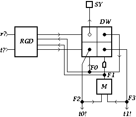
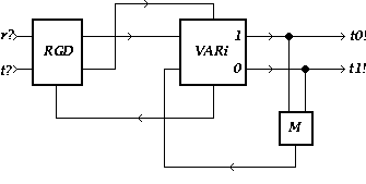
Schematic diagram
for a Test-and-Set:

[Zoom|FIG]
XDI state graph
for a Test-and-Set:

[Zoom|FIG]
Specification in XDI model.
No information available
Specification in DI Algebra:
NAME = "Test and set (dial)"
I = { r?, t? }
O = { t0!, t1! }
TS = [ r? -> TS0
     , t? -> t1!; TS
     ]
TS0= t?; t0!; TS
Also available through this link
XDI Report.
The Test-and-Set is output nondeterministic. This
nondeterminism is dynamic.
Last modified at Fri Nov 20 10:11:41 1998
Encyclopaedia of Delay-Insensitive Systems
Copyright © 1995-1998
Tom Verhoeff /
Tom.Verhoeff@acm.org


