EDIS:
Guide |
FAQ |
New |
Search |
Bibliography |
Index |
Feedback
Non-receptive Test-and-Set
Informal
A Non-receptive Test-and-Set has two input terminals t and
r, and three output terminals a,
t0 and t1. The 'state' of
a Non-receptive Test-and-Set is initially '1' and is reset to '0'
by a signal on input r. The reset is acknowledged by a signal on
a. The current state is tested and set to '1' by
a signal on input t. The result of the test is relayed to the
environment as either a t0 or a t1 signal.
A reset is not allowed unless the state is '1'.
The Non-receptive Test-and-Set is non-receptive in the sense
that the environment must guarantuee mutual exclusion of requests on t and
r. There is also a receptive variant, called
the Test-and-Set.
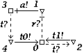
Schematic diagram
for a Non-receptive Test-and-Set:

[Zoom|FIG]
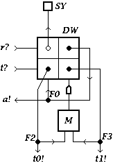
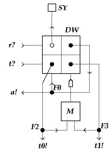
XDI state graph
for a Non-receptive Test-and-Set:
[Zoom|FIG]
Specification in XDI model.
[LET OP: spec file spec-1.dec niet te openen! (No such file or directory)]
Specification in DI Algebra:
NAME = "Non-receptive Test-and-Set [dial]"
I = {r?, t? }
O = {a!, t0!, t1!}
TS = [ r? -> [a! -> TS0, t? -> CHAOS]
     , t? -> [t1! -> TS, r? -> CHAOS]
     ]
TS0 = [r? -> CHAOS, t? -> t0!;TS]
Also available through this link
XDI Report.